Simulations using Forma
Autodesk Forma (formerly Spacemaker) helps planning and design teams deliver projects digitally from day one. Use conceptual design capabilities, predictive analytics, and automations to make solid, sustainable, foundations for your projects. (https://www.autodesk.com/products/forma/) Forma enables to run Daylight potential analysis | Area analysis | Microclimate analysis | Noise analysis | Rapid Operational Energy analysis | Sun hours analysis | Wind analysis.
Uploading data
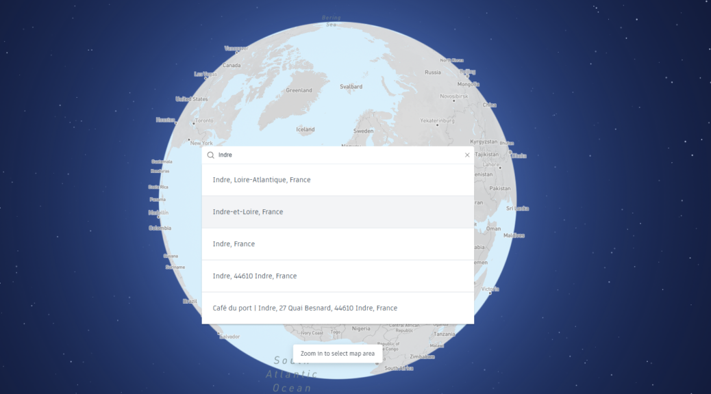
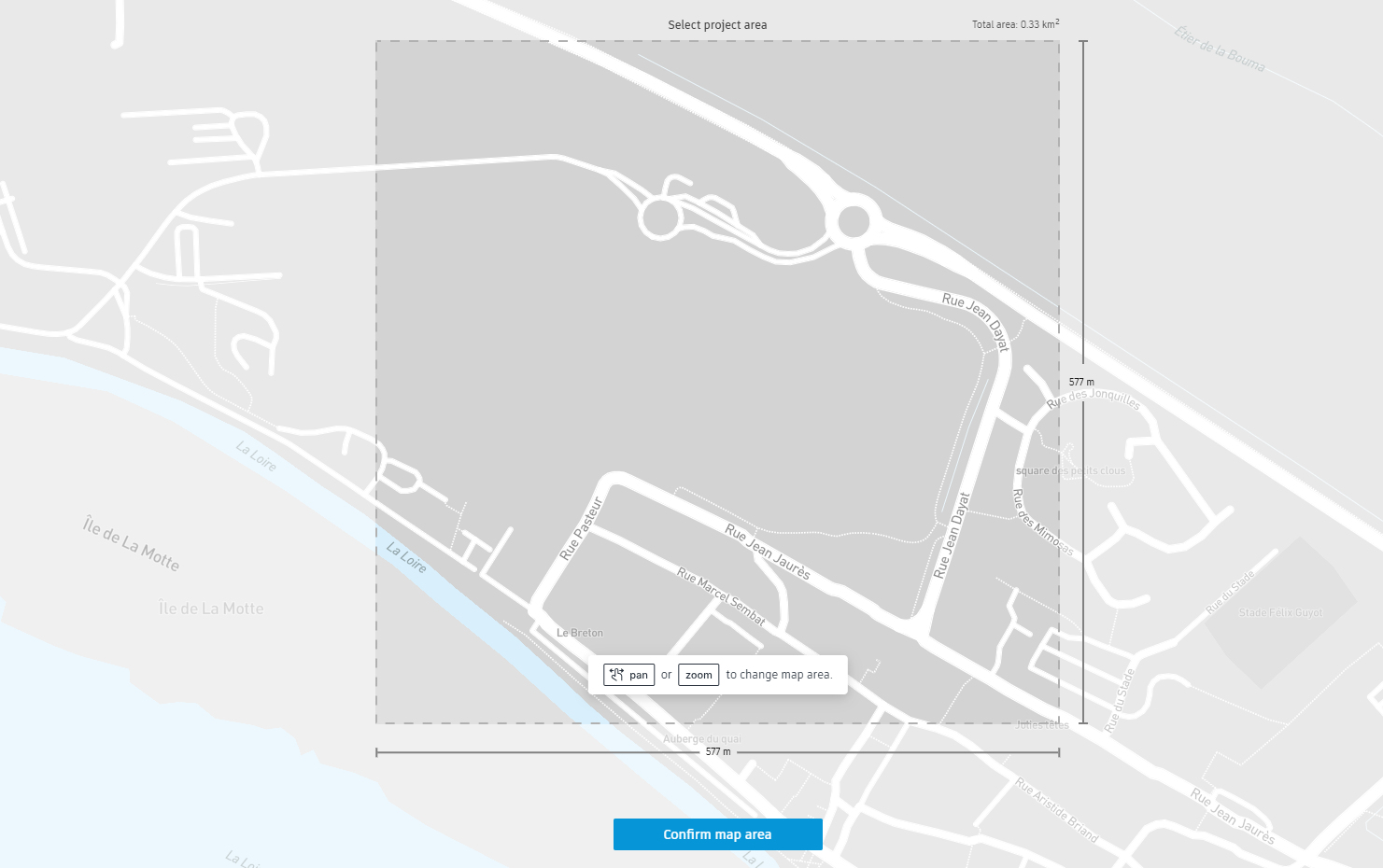
The site is located from the map.
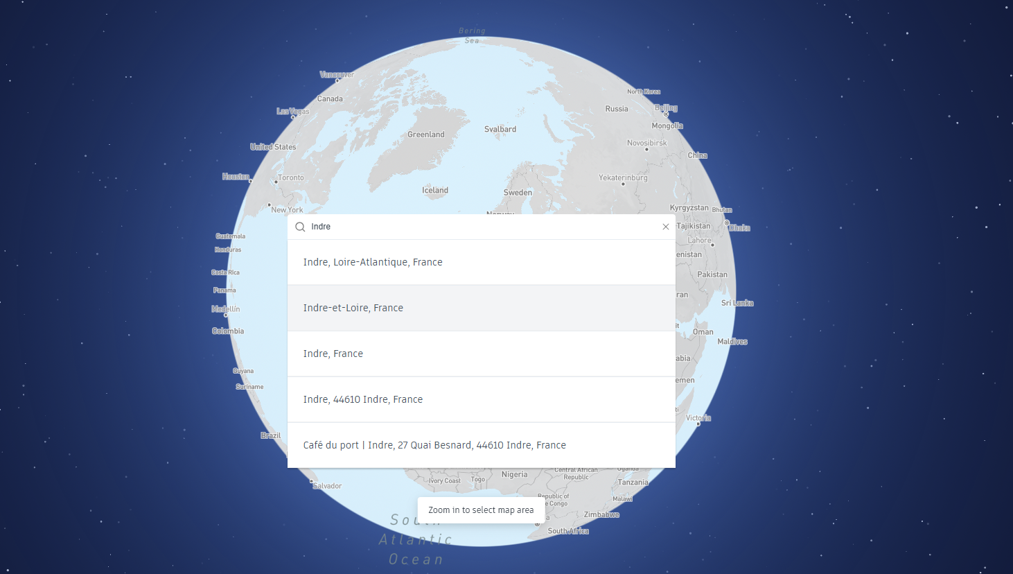
Then the area is selected, zooming in and out allows to extract the desired area.
It is then possible to directly add contextual data. It can also be added later.
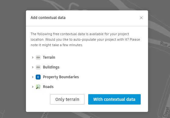
The site is then populated with data. You can also import site data from various sources, such as GIS datasets, CAD files, or 3D models. Autodesk Forma also allows direct access to built-in mapping tools, providing accurate terrain, infrastructure, and zoning data for many locations worldwide. Once the data is imported, Autodesk Forma visualizes the site with all its elements, giving a clear and interactive overview of the project context. At this stage, it is possible to assess the site’s constraints and potential.
Site limit
Creating site limits in Autodesk Forma is a crucial step to clearly outline the boundaries of your project within the imported context. This phase focuses on isolating the specific area for design and analysis, ensuring that all tools and simulations are tailored to the intended scope.
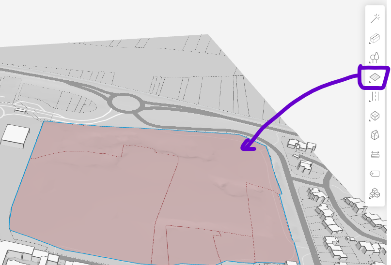
The process of defining site limits in Autodesk Forma begins with the use of polygonal drawing tools to establish the boundaries of the project area. To create a polygon, points are placed sequentially on the canvas, with each point marking a vertex of the boundary. The process is completed by connecting the final point back to the first, thereby closing the shape and defining the enclosed area.
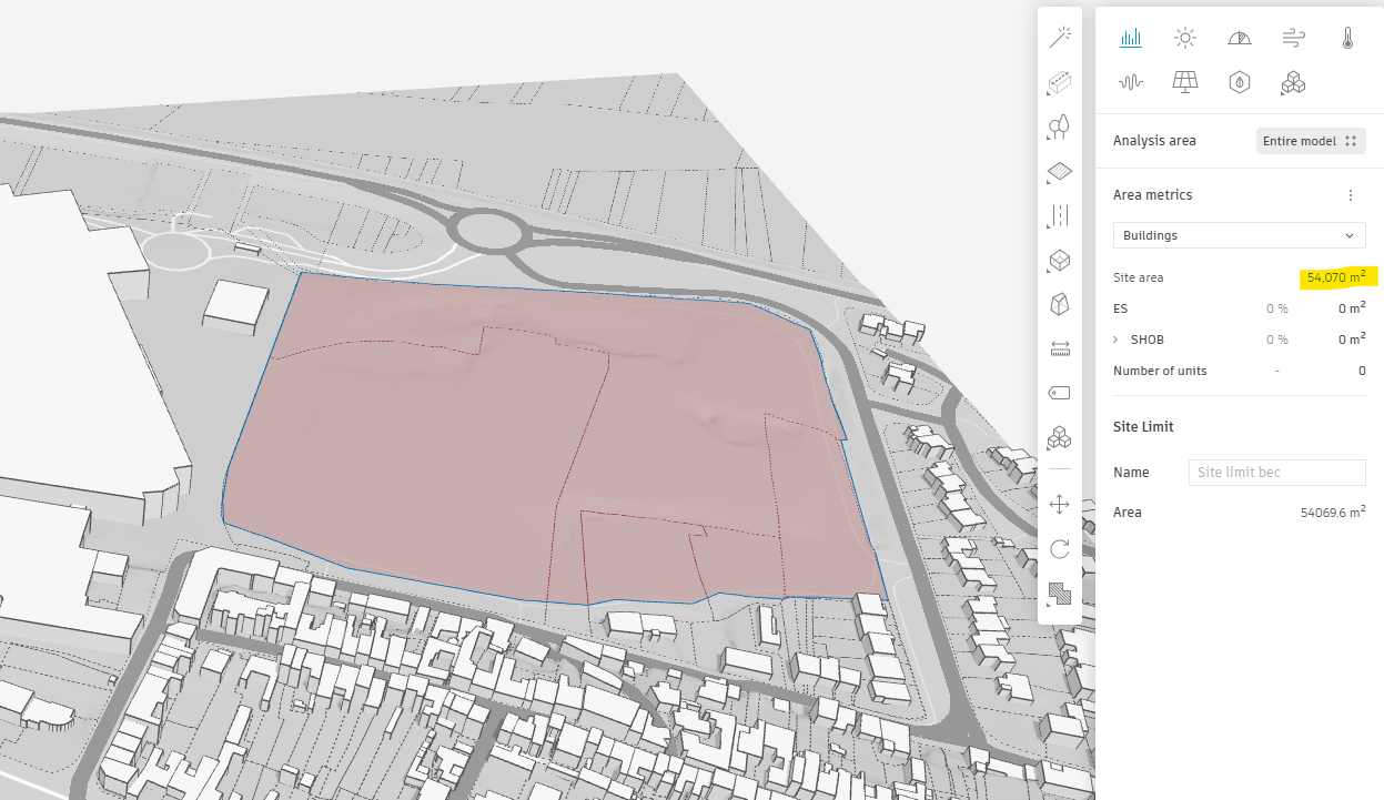
As the boundary is defined, the total surface area of the enclosed site is automatically calculated and displayed in the Area Metrics panel. This feature provides immediate feedback on the size of the defined project area, aiding in decision-making and ensuring alignment with project requirements.
This defined boundary allows all subsequent workflows to focus on the intended scope of the project while maintaining clarity and context within the surrounding environment.
Exploring Design Variations in Autodesk Forma
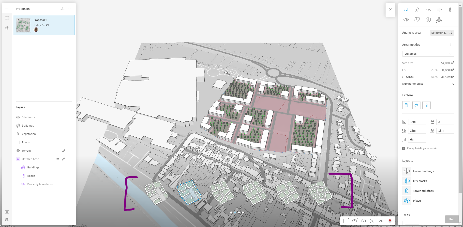
The Explore procedure in Autodesk Forma provides a dynamic method for generating and evaluating multiple design variations within the defined site limits. This feature leverages computational algorithms to produce randomized design solutions, offering a broad spectrum of possibilities to inspire and inform the conceptual design process.

Using the defined constraints, Forma generates a series of randomized building configurations. Each iteration is unique, providing a variety of massing layouts and spatial arrangements. The randomness encourages innovative solutions and highlights unexpected opportunities within the project site.
The generated designs are visualized in 3D, allowing for an immediate assessment of their spatial and aesthetic qualities. Key metrics, such as floor area, building height, or site coverage, are displayed alongside each variation, offering a quantitative comparison of the options.
Filters can be applied to narrow down the options based on specific criteria, such as maximizing sunlight exposure, minimizing wind impact, or achieving a desired density. Adjustments to the constraints can also be made to refine the generated results further.
This defined boundary allows all subsequent workflows to focus on the intended scope of the project while maintaining clarity and context within the surrounding environment.
Creating units
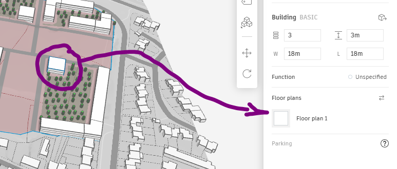
The creation of a basic layout for living units
in Autodesk Forma involves the use of the Floor Plans tool. This feature allows for the definition of internal spaces and the arrangement of rooms within a building massing, providing a clear framework for functional living unit layouts.
Living unit boundaries are established by drawing dividing walls. Walls are created by clicking and dragging within the floor plan view, connecting endpoints to form enclosed spaces. These spaces represent the basic structure of individual units.
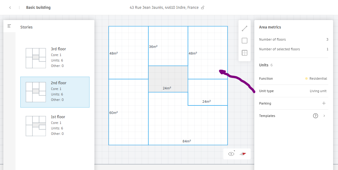
Circulation areas, such as corridors and entrances, are planned to ensure efficient movement within the layout. Pathways between functional areas are designed with accessibility and practicality in mind.
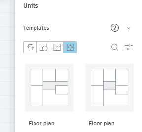 Once finalized, the floor plan can be saved as a template for future use or further refinement. This allows for consistency across multiple floors or similar projects.
The Area metrics are updated I, terms on number of units and surfaces.
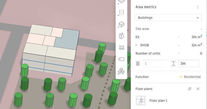
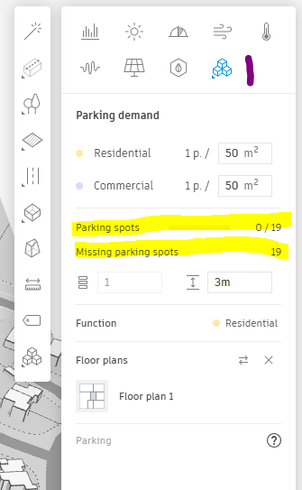
In the Extension tab, the Parking Demand Calculator evaluates the number of required parking depending to units created.
Creating parking
The TestFit extension in Autodesk Forma streamlines the process of designing and optimizing parking layouts. By leveraging parametric algorithms, this tool generates efficient and compliant parking arrangements within the site or building boundary.
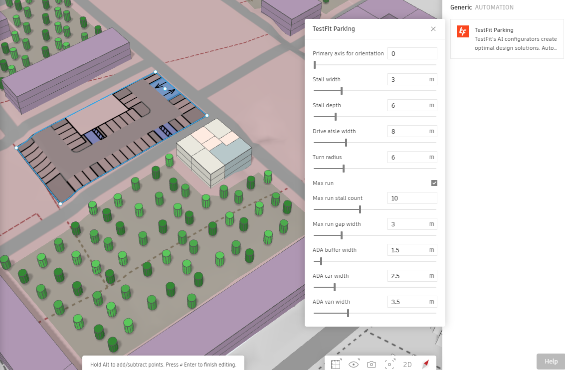
The area designated for parking is selected or drawn. This can be an open lot, a portion of a building’s ground floor, or an underground level. The boundaries of the parking area serve as the framework for the layout.
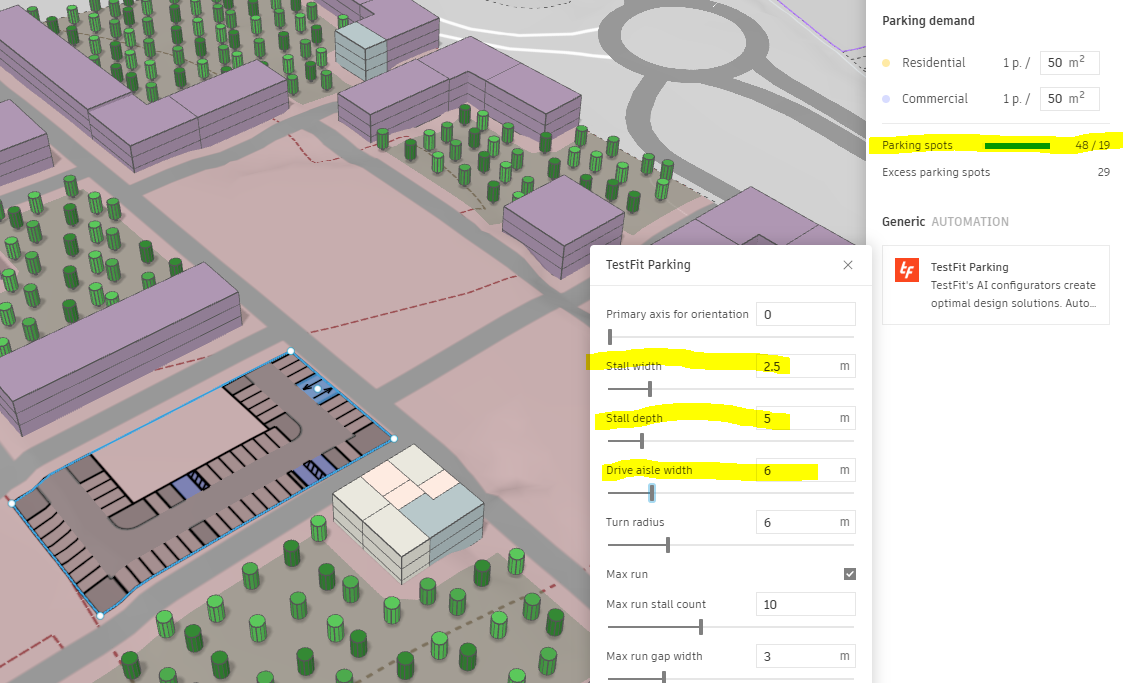
The parameters for the parking design include: Parking Space Dimensions: Specify the standard size for individual parking spaces based on local regulations. Drive Aisle Width: Define the width of aisles for vehicle circulation. Access Points: Indicate entry and exit locations for vehicles.
The parking need is automatically updated.
Isovists, view analysis
The View Analysis extension in Autodesk Forma is a powerful tool for evaluating the visual accessibility and quality of views from a given site or building. This extension enables designers to assess sightlines, optimize building placement, and enhance the visual experience of occupants by considering the surrounding context.
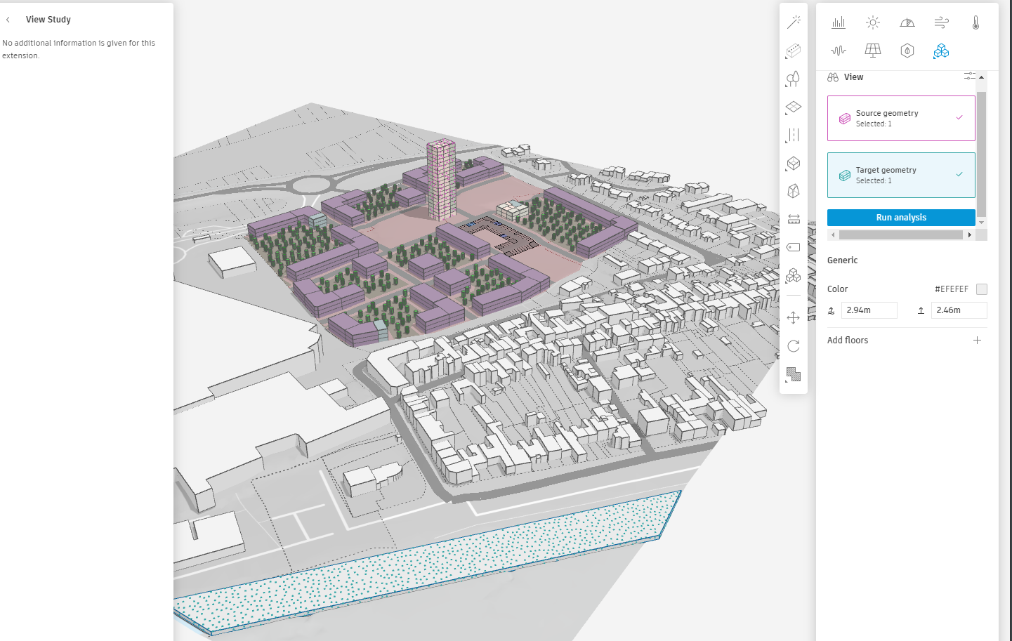
The View Analysis extension is accessed from the analysis tools within Forma. It can be applied to entire buildings, specific floors, or individual units to evaluate the visibility of key external elements.
Observation points, or vantage points, are selected or placed within the design. These points represent locations such as windows, balconies, or public spaces from which views are to be analysed.
Targets are defined in the surrounding context, such as landmarks, natural features, or other points of interest. These can be set manually or selected from contextual layers imported into Forma (e.g., a city skyline or nearby park).
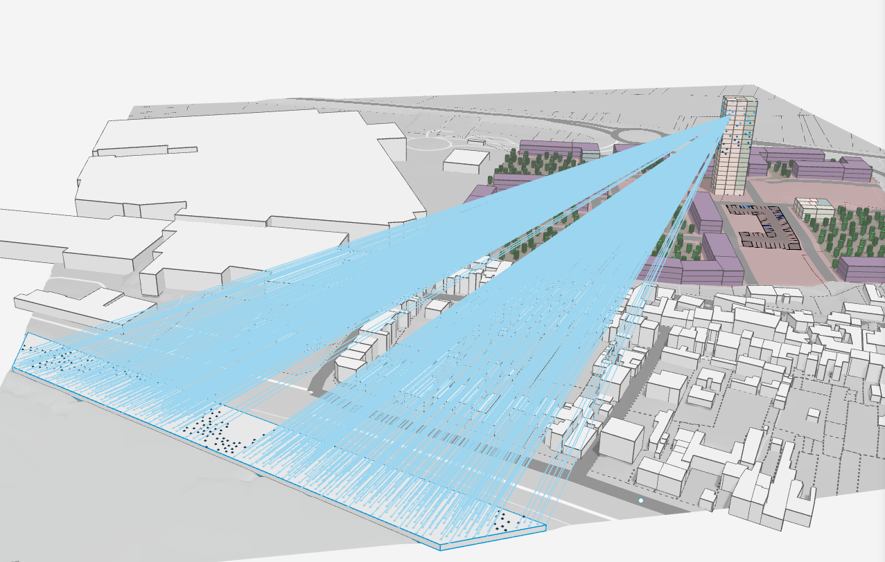
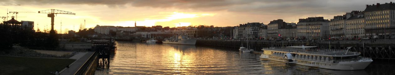
In this example, the system verifies from which floor the water is seen beyond the hill.
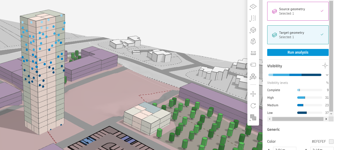
The tool calculates and visualizes sightlines from the observation points to the targets.
The visual output allows for a comprehensive assessment of the site’s visual potential. Key metrics include the percentage of unobstructed views, the number of target points visible, and the quality of sightlines.
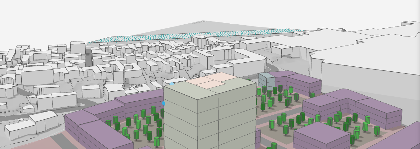
View line from one source.